Exam Summer 2014


Introduction
As the old Hergiswald Bridge by Jospeh Ritter from 1791 no longer met the latest requirements, the municipality of Kriens planned a bypass to the north of the old bridge, and in 2009, called for a competition to design a new bridge. The new bridge, designed by a team of civil engineers around Fuerst Laffranchi together with Ilg Santer Architects, relates in form and materialization to the adjacent historic bridge. The bridge beam with a bottom chord in tension is a reflection of the compression arch of the old bridge. The key structural elements of the new bridge are kept in timber as in the historic bridge. The first and third part of the exercise are related directly to the bridge and include dimensioning and calculations, parts two and four target general knowledge related to arches and frames in a qualitative manner.
The bridge as an arch-cable structure
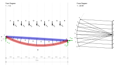
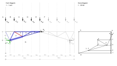
In the first part of the exercise, a simplified version of the Hergiswald Bridge will be analyzed. The bridge structure spans 32 metres and has a width of 2.4 metres. It is supported at points 1 and 2 with a height difference of 4 metres. The bridge consists of two cable-supported beams that are loaded with a a live load wq = 5.0 kN/m2 and a dead load wg = 1.0 kN/m2. These loads act as seven equal vertical point loads Pd at the respective nodes of the structure.
- Calculate the design load Pd which is acting on each node of the two cable-supported beams and indicate its value in kN (Step 1)
- Label the spaces in the form diagram and construct the load line. Ignore your result and assume Pd = 50 kN (Step 2).
- Determine the reaction forces graphically, using a trial funicular construction. Indicate the magnitude and direction of the reaction forces (Step 3).
- For the bottom chord, a steel cable (S500, diameter d = 35 mm) is used. Calculate the maximum force that this cable can carry. Find the geometry of the cable-supported beam such that a constant force equal to the calculated maximum cable force is acting in the bottom chord (Step 4-6).
- Indicate the character of all member forces using red for tension and blue for compression (Step 7).
- Determine the maximum force in the top chord and indicate its value in kN (Step 8).
- The top chord of the cable-supported beam consists of a laminated timber profile with a width b = 200 mm. Determine the height h of the cross-section of the laminated timber profile and indicate its value rounded to centimeters (Step 9).
Click here to open the interactive drawing that shows the graphical solution. Use the slider to browse through the different steps of the construction.
Form and forces of arch structures
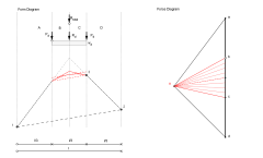
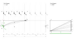
The second part of the exercise deals with the form of arch structures and the forces acting in them. Use the relationship between loading and funicular geometry to determine the shape of the different arch structures graphically.
- Draw the funicular shape of the arch for the four different load cases. The arch is supported in points 1 and 2 and pass through point 3.
Click here to open the interactive drawing that shows the graphical solution. Use the check boxes to switch between the different load cases. Use the slider to browse through the different steps of the construction.
Click here to open the interactive drawing that shows the graphical solution. Use the check boxes to switch between the different load cases. Use the slider to browse through the different steps of the construction.
- Consider two arches side-by-side. The form and force diagram for the left arch are given. It spans between points 1 and 2 and passes through point 3. It is loaded by a uniformly distributed load wd between points 3 and 2. The right arch spans between points 2 and 4 and is loaded with the same uniformly distributed load wd which is applied to its entire span.
- Find the funicular form of the right arch such that both arches have the same horizontal reaction force (scenario a).
- Find the funicular form of the right arch such that its rise is equal to the height of point 3 (scenario b).
Click here to open the interactive drawing that shows the graphical solution. Use the check boxes to switch between the different scenarios. Use the slider to browse through the different steps of the construction.
The bridge as a three-hinged truss frame
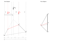
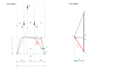
In the third part of the exercise, a three-hinged truss frame as an alternative to the Hergiswald Bridge will be analyzed. The bridge structure spans 28 metres and has a frame height of 4 metres. It is supported at points 1 and 2, the hinge is located at point 3. The nodes of the truss frame are loaded with point loads Pd1 = 50 kN and Pd2 = 25 kN respectively.
- Determine if the truss is statically determinate (Step 1).
- Due to the symmetry of the structure we only consider the part between support 1 and the hinge 3. Note that a horizontal force H3 has to be added, representing the action of the right-hand part of the structure on the left-hand part of the structure. Label the spaces in the form diagram and construct the loadline (Step 2).
- Determine the reaction forces of the truss frame and H3 graphically (Steps 3-4).
- Determine the magnitude of the reaction forces and H3 (Step 5).
- Find the magnitude of all the member forces and indicate their valuex in kN (Steps 6-7).
- Indicate the character of all member forces using red for tension and blue for compression (Step 8-10).
- Determine the critical member of the truss frame and indicate its magnitude in kN (Step 11).
- Dimension the critical truss member as a HEA profile (S355) (Step 12).
Click here to open the interactive drawing that shows the graphical solution. Use the slider to browse through the different steps of the construction.
Given is a rigid frame with the same loading, support conditions and hinge location.
- Due to the symmetry of the structure we only consider the part between support 1 and the hinge 3. Note that a horizontal force H3 has to be added, representing the action of the right-hand part of the structure on the left-hand part of the structure. Label the spaces in the form diagram and construct the loadline (Step 1).
- Determine the reaction forces of the frame and H3 graphically (Steps 2-4).
- Find the thrust line of the frame as a funicular form for the set of point loads Pd1 and Pd2 (Step 5).
- Determine the critical bending moment M_{max} in the frame using the found thrust line, its force diagram and the frame's geometry (Step 6).
- Confirm that the HEA 220 profile (S355) previous calculated can be used for the frame. If it is not sufficient, dimension an appropriate profile (Step 7).
Click here to open the interactive drawing that shows the graphical solution. Use the slider to browse through the different steps of the construction.
Qualitative analysis of a rigid frame
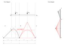
The fourth part of the exercise deals with the structural behaviour of rigid frames. Given is a rigid three-hinged frame with at points 1 and 2 and a hinge at point 3. It is loaded with two point loads Pd2 = 2 x Pd1.
- Determine the thrust line of the frame as a bending-free form, i.e. the funicular form, for the given loading and hinge location and draw the form and force diagram (Steps 1-3).
- Determine the critical bending moment in the frame using the found thrust line, its force diagram and the frame's geometry (Steps 4-5).
Click here to open the interactive drawing that shows the graphical solution. Use the slider to browse through the different steps of the construction.